Subsections
Experiments
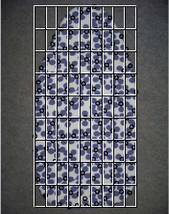
We generate two images by simulating two cameras looking at a surface with different deformations between the views.
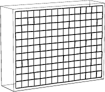
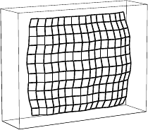
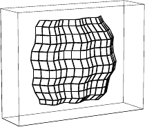
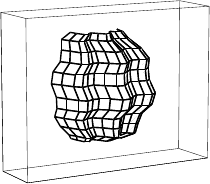
The surface is generated as a linear combination of two objects: a simple plane and a more deformed surface (see figure 6.4).
A single parameter,  , controls the amount of surface bending.
Points on the surface are projected on the images and corrupted with an additive gaussian noise.
The perspective effect is controlled by varying the distance between the scene and the camera (the focal length,
, controls the amount of surface bending.
Points on the surface are projected on the images and corrupted with an additive gaussian noise.
The perspective effect is controlled by varying the distance between the scene and the camera (the focal length,  , is adjusted so that the apparent size of the imaged surface remains approximately the same).
The influence of three quantities are tested independently:
, is adjusted so that the apparent size of the imaged surface remains approximately the same).
The influence of three quantities are tested independently:
- the amount of noise: controlled by the standard deviation
 in pixels;
-
the amount of bending: controlled by the previously described parameter ;
-
the amount of perspective: controlled by the scene to camera distance  , in pixels.
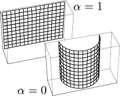
Figure 6.4:
The simulated threedimensional surfaces used in our experiments are obtained as linear combinations of a plane ( ) and of a more distorted surface (
 ).
).
|
|
The default simulation parameters are  point correspondences,
 pixel,
 ,
,  pixels,
  pixels and
  control points.
These parameters yield mild perspective effects.
For each set of parameters, the generated surface is also rotated around its center.
The reported results are the average of the mean transfer error over 100 surfaces which have different rotations and corruptions of the projected points.
For each varied parameter, three plots report the results for different numbers of control points (
control points.
These parameters yield mild perspective effects.
For each set of parameters, the generated surface is also rotated around its center.
The reported results are the average of the mean transfer error over 100 surfaces which have different rotations and corruptions of the projected points.
For each varied parameter, three plots report the results for different numbers of control points ( ,
,  and
and  ).
Four curves are reported on each plot.
They correspond to the homographic warp, the initial estimate of the NURBS-Warp using the algebraic distance, the optimal BS-Warp and the final NURBS-Warp.
).
Four curves are reported on each plot.
They correspond to the homographic warp, the initial estimate of the NURBS-Warp using the algebraic distance, the optimal BS-Warp and the final NURBS-Warp.
Two general observations can be made about those results.
First, the experiments show that the NURBS-Warp always outperforms the three other approaches.
This comes from the fact that it is designed, by construction, to model more complex deformations between images6.2.
Second, the following results show that the larger the number of control points, the lower the transfer error.
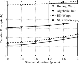
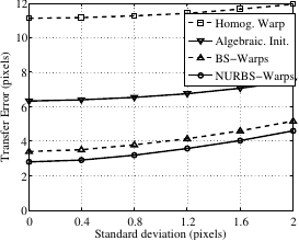
Figure 6.5 shows the influence of the amount of noise on the estimated warps.
We can see that the influence of this factor is relatively limited and, more importantly, that this influence is similar for all the four warps.
Figure 6.5:
The influence of the amount of noise.
|
|
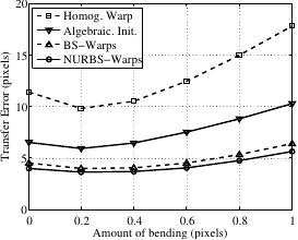
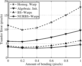
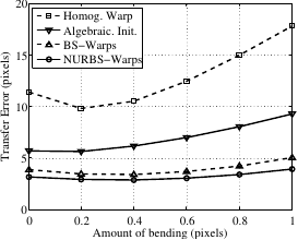
The influence of the amount of bending is studied by varying the parameter .
The results are reported in figure 6.6.
This experiment shows, as expected, that the homographic warp is the one which is the most influenced by the deformations of the observed surface.
It comes from the fact that the homographic warp inherently does not model deformable environments.
Figure 6.6:
The influence of the amount of bending.
|
|
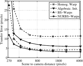
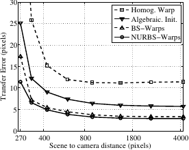
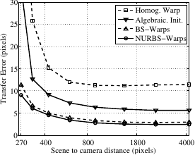
The influence of the perspective effect is studied by varying the scene to camera distance: the larger the distance, the more affine the imaging conditions.
The results are reported in figure 6.7.
This experiment truly reveals the full power of the proposed NURBS-Warp.
Indeed, for the lowest number of control points (), we see that with an important perspective effect ( ), the NURBS-Warp is more than twice as good as the BS-Warp.
Two main reasons explain this result.
First, the NURBS-Warp has been designed to model perspective effects.
Second, the behavior of the BS-Warp is better for affine imaging conditions.
Figure 6.7 also shows that the BS-Warp can correctly model the deformations but it requires a large amount of control points.
), the NURBS-Warp is more than twice as good as the BS-Warp.
Two main reasons explain this result.
First, the NURBS-Warp has been designed to model perspective effects.
Second, the behavior of the BS-Warp is better for affine imaging conditions.
Figure 6.7 also shows that the BS-Warp can correctly model the deformations but it requires a large amount of control points.
Figure 6.7:
The influence of the amount of perspective.
|
|
In the previous experiment the warps had to cope simultaneously with perspective effects and large surface deformations.
As a consequence, it is difficult to see the benefit brought by our NURBS-Warp.
We thus present the influence of perspective with less complex deformations.
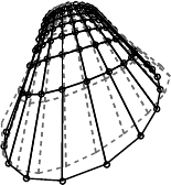
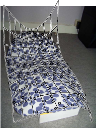
We use the same experimental setup except for the generated surface which is now obtained as the linear combination of a plane and a half-cylinder (see figure 6.8 a).
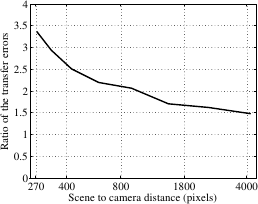
Figure 6.8 c shows that the NURBS-Warp brings a real benefit compared to the BS-Warp when the perspective effect are important: for example, we see that compared to the BS-Warp, the NURBS-Warp transfer error is over 3 times lower for a camera to scene distance of 270 pixels.
Figure 6.8:
(a) Simple deformations are obtained using a linear combination of a plane and a half-cylinder. (b) The NURBS-Warp (black visualization grid) models better the perpective effect than the BS-Warp (dashed grid). The black circles represent the ground truth location of the vertices. (c) The BS-Warp transfer error divided by the one of the NURBS-Warp.
|
|
From the last two experiments, we can say that the proposed NURBS-Warp is well suited for large perspective effects.
However, when the surface deformations are significant, both the NURBS-Warp and the BS-Warp require a lot of control points.
Since it increases the number of degree of freedom, the BS-Warp can also cope with perspective effects.
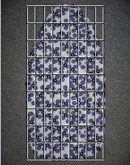
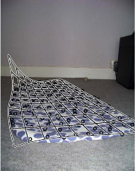
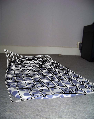
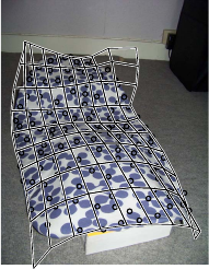
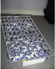
Figure 6.9 and figure 6.10 show examples of warps estimated for a rigid and a deformable scene respectively.
The warps are estimated from 130 point correspondences that we entered manually (represented by the small circles).
We set the number of control points to 16 for both the BS-Warp and the NURBS-Warp.
The estimated warps are represented by a visualization grid.
This grid is shown in its rest position in the first image.
It is then transferred into the second image using the estimated warps.
The conclusion of this experiment is that the NURBS-Warp is the one that gives the best results.
This is especially true when perspective effects and surface deformations are combined.
In particular, we can see in figure 6.10 that the NURBS-Warp is the only warp able to retrieve realistic surface deformations.
Note that the transfer errors reported in figure 6.9 and figure 6.10 may seem important.
These high values come from the fact that the images have a quite high resolution (approximately
 pixels).
Figure 6.9:
Warps estimated for a rigid surface (TE: Transfer Error in pixels).
|
|
Figure 6.10:
Warps estimated for a deformable scene (TE: Transfer Error in pixels).
|
|
Contributions to Parametric Image Registration and 3D Surface Reconstruction (Ph.D. dissertation, November 2010) - Florent Brunet
Webpage generated on July 2011
PDF version (11 Mo)